EVA Netmodeler Visual Modeling XML.
This section covers the following topics:
There are two distinct types of modeling in EVA Netmodeler, namely Meta Modeling (for modeling meta data) and Instance Modeling (for modeling instance data).
Meta Modeling Overview
Meta modeling works exactly like instance modeling, except that we are not modeling EVA Netmodeler items themselves, but rather the meta-definition for these items. In order to represent this
information visually, we require the following:
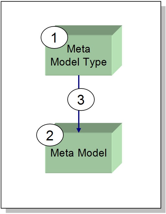
- An EVA Netmodeler instance of type "Meta Model Type" describing the mapping between visual object types and EVA Netmodeler NodeTypes. This differs from the instance model type in the sense that there is only one visual
type for every EVA Netmodeler nodetype and one visual type for every EVA Netmodeler RelType.
- An EVA Netmodeler instance of type "Meta Model" containing all information needed to represent the model visually. This includes co-ordinates, size and so forth.
The Meta Model instance also describes the contents of the model by nominating a specific "Domain". Information
in a domain can be filtered by using the "EXCLUDE" xml tags (see discussion below for more detail on how this is done).
- A relationship between the "Meta Model Type" and the "Meta Model".

The "Meta Model Type"
This type is used to define a mapping between visual (graphical) objects and EVA Netmodeler NodeTypes. Since we are trying to represent meta-data, all EVA Netmodeler
NodeTypes will be drawn using the same visual type. Also, all EVA Netmodeler RelTypes will be drawn using the same visual type.
It is recommended that you use the UML stencil for this type of model. Consequently, you have little choice but to use
the "Class" master in the UML stencil for Archi NodeTypes and the "binary association" master for Archi RelTypes.
In order to create this mapping, you can use the XML shown below:
<METAMODELTYPE>
<VISUALNODETYPE>Class</VISUALNODETYPE>
<VISUALRELTYPE>Binary Association</VISUALRELTYPE>
</METAMODELTYPE>

The "Meta Model"
This EVA Netmodeler type is used to define the contents of a Graphical meta model. As mentioned before, since we are
modeling meta-data, we cannot create a link between a "Meta-Model" instance and the meta definitions themselves. Consequently we have to store all graphical information in the "Meta Model" instances themselves.
This is done by adding a "Model description" attribute to the "Meta Model" type and storing graphical information as XML in this attribute.
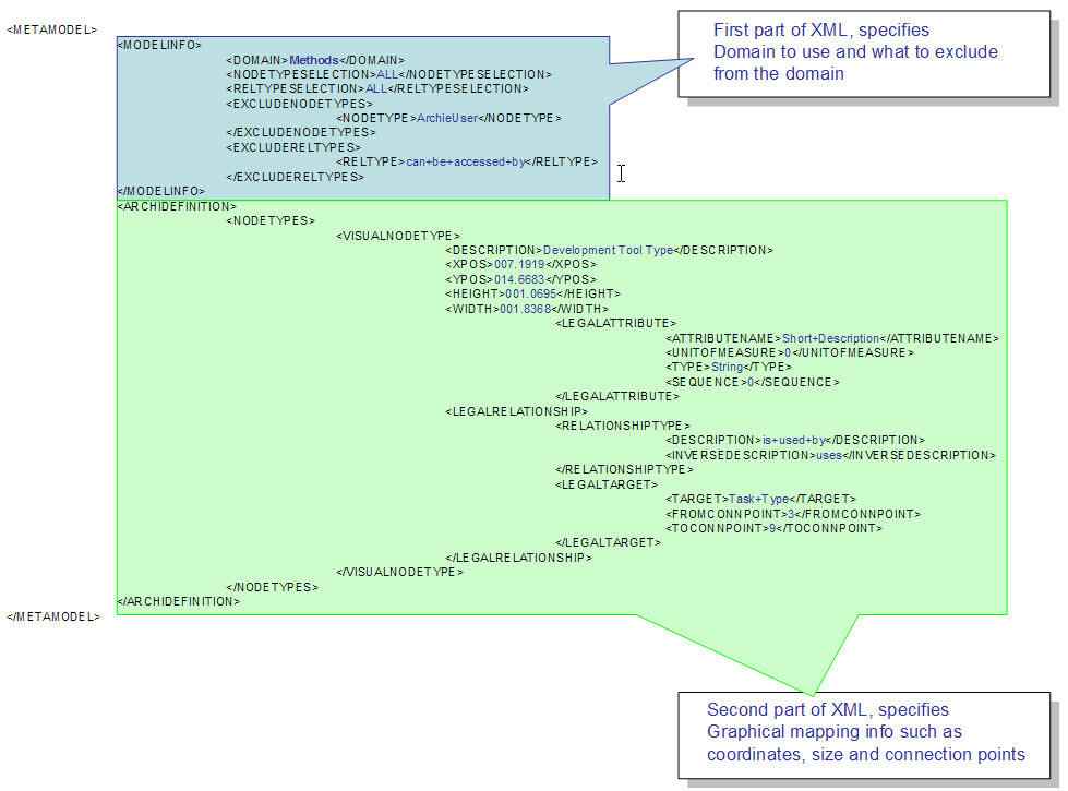
The XML consists of two parts, the first part is used to define the contents of the model by nominating an EVA Netmodeler
Domain, all NodeTypes encapsulated by that domain will be included in the model.
However, since we may want to exclude certain types without having to create a new domain, there is a facility to exclude either NodeType or RelTypes.
The second part of the XML is used to contain the graphical mapping information for the NodeTypes in the model, such
as X and Y co-ordinates, height, width and so forth. This part of the XML is designed to look almost exactly like the XML obtained when exporting meta-data from EVA Netmodeler.
The Meta Modeling facility is currently limited to extracting meta model fragments so that they can be laid out in Visio and
saved as a Visio diagram. No facility exists to save the meta model diagram back to the repository. A subsequent release may provide a tool that will propagate meta-models back into the repository.

Instance Modeling Overview
In order to present EVA Netmodeler Knowledge Items graphically, the following minimum requirements are needed:
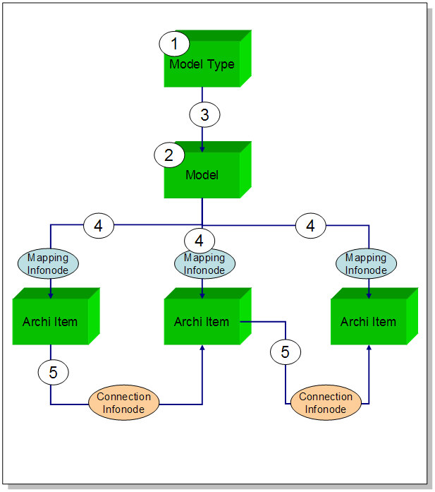
- A knowledge item describing the mapping between visual object types and EVA Netmodeler Types (Referred to as a "Model Type")
- A knowledge item describing the contents of the visual model to be represented (Referred to as a "Model").
- A relationship between the "Model Type" and the "Model".
- A relationship between the contents of the "Model", in other words the EVA Netmodeler Knowledge Items and the "Model" instance. This relationship must have an Info Node that can contain graphical modeling specific
information such as the coordinates where the graphical item must be drawn and the size of the graphical item.
- Relationships between the "Model" content items themselves, since these relationships will be drawn graphically as "connectors" between two objects, it must have an infonode in
EVA Netmodeler that is capable of storing the connection points as well as the "text" describing the connector.

The "Model Type"
This type is used to define a mapping between visual (graphical) objects and EVA Netmodeler objects. For example, if we have a Visio stencil with the following masters:
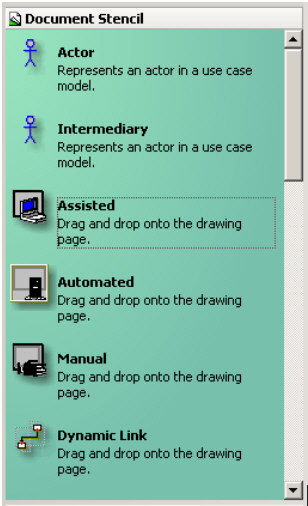
We must create a mapping between the Visio objects and the EVA Netmodeler types. This is done by providing some
XML to the "Model Description" property of a "Model Type" instance. This section describes this feature by way of worked examples. Refer to the Model Type XML Specification section for a more formal specification of the Model Type
XML.
Type Mappings
We can either create a "simple" or direct mapping (e.g. "Actor" to "Person", "Assisted" to "Assisted Process Step" and so forth) with the following XML:
<MODELTYPE>
<NODEMAPPING>
<ARCHITYPE>Person
</ARCHITYPE>
<VISUALTYPE>Actor
</VISUALTYPE>
</NODEMAPPING>
<NODEMAPPING>
<ARCHITYPE>Assisted Process Step
</ARCHITYPE>
<VISUALTYPE>Assisted
</VISUALTYPE>
</NODEMAPPING>
<NODEMAPPING>
<ARCHITYPE>
Automated Process Step</ARCHITYPE>
<VISUALTYPE>Automated
</VISUALTYPE>
</NODEMAPPING>
</MODELTYPE>
An <ARCHITYPE> is what the node is called in EVA Netmodeler while the <VISUALTYPE> is what the node is called in Visio.
Additional Mappings
It is possible for more than one Visio shape to map to the same EVA Netmodeler node type. For example, we can map all three of the Visio shapes "Automated", "Assisted" and "Manual" to the EVA Netmodeler
type "Process Step". However, when we extract the model from EVA Netmodeler, EVA Netmodeler will be unable to distinguish between the "Process
Steps" and therefore be unable to provide sufficient information to enable us to re-create the visual model faithfully. We therefore need to provide additional mapping information. This can be done in two ways:
- We can use a property of the "Process Step" type to distinguish between the various steps. For example, we can map "Automated" to "Process Step", with the additional mapping proviso that a property named "Step Type" must
have a value of "AUTOMATED". We also map "Assisted" to "Process Step" with the additional mapping proviso that the "Step Type" property must have a value of "ASSISTED" and so forth. The XML for this type of mapping will
be as follows:
<MODELTYPE>
<NODEMAPPING>
<ARCHITYPE>Process Step
</ARCHITYPE>
<VISUALTYPE>Assisted
</VISUALTYPE>
<ADDITIONALMAPPINGINFO>
<ATTRIBUTE>
<ATTRIBNAME>
Step Type</ATTRIBNAME>
<ATTRIBVALUE>
ASSISTED</ATTRIBVALUE>
</ATTRIBUTE>
</ADDITIONALMAPPINGINFO>
</NODEMAPPING>
</MODELTYPE>
- We can use a relationship to an item of another type to distinguish between the various steps. For example, we can map "Automated" to "Process Step", with the additional mapping proviso that the "Process Step" instance
must have an "is type of" relationship to EVA Netmodeler type "Step Type" and instance "Automated", the XML for this type of mapping will be as follows:
<MODELTYPE>
<NODEMAPPING>
<ARCHITYPE>Process Step
</ARCHITYPE>
<VISUALTYPE>Automated
</VISUALTYPE>
<ADDITIONALMAPPINGINFO>
<RELTYPE>
<RELTYPENAME>
is kind of</RELTYPENAME>
</RELTYPE>
</ADDITIONALMAPPINGINFO>
</NODEMAPPING>
</MODELTYPE>
Attribute Mapping
In addition to mapping visual types to EVA Netmodeler types, you can also map Visual properties to EVA Netmodeler attributes as is shown in the XML below:
<MODELTYPE>
<NODETYPEATTRIBUTE>
<ARCHIATTRIBUTE>
AA_Description</ARCHIATTRIBUTE>
<VISUALATTRIBUTE>
Description</VISUALATTRIBUTE>
<ATTRIBUTETYPE>
Archie2Discussion</ATTRIBUTETYPE>
</NODETYPEATTRIBUTE>
<NODETYPEATTRIBUTE>
<ARCHIATTRIBUTE>
AA_DurationMin</ARCHIATTRIBUTE>
<VISUALATTRIBUTE>
DurationMin</VISUALATTRIBUTE>
<ATTRIBUTETYPE>
Archie2Decimal</ATTRIBUTETYPE>
</NODETYPEATTRIBUTE>
</MODELTYPE>
Relationship mappings
Relationship mappings work similarly to node mappings. As before, we need to map shapes used to represent relationships in Visio to relationship types in EVA Netmodeler.
<MODELTYPE>
<ARCHIRELTYPE>includes parts</ARCHIRELTYPE>
<VISUALTYPE>Composition</VISUALTYPE>
</MODELTYPE>
Above is a mapping for the UMLcontainment relationship type. In Visio it is known as Composition and in EVA Netmodeler it is known as includes parts. In general, the naming of Visio types and EVA Netmodeler
types are up to the users so it would be a good idea to have a strict naming convention standard which all the users follow. This will prevent XML mapping errors due to incorrect attribute, relationship and/or node definitions.
This is the simplest form of RelType mapping, and declares that when a model is retrieved from EVA Netmodeler, all relationships using includes parts will be represented with a visual type of Composition.
However, you may want to use the same visual type to represent different types of EVA Netmodeler Reltype. For example, if you have a "Person" and a "Process" type in EVA Netmodeler, with a relationship between persons using
the "is related to" RelType and a relationship between processes using the "invokes process" RelType, and you want to model it using the same visual type, you must have use the following XML;
<MODELTYPE>
<RELMAPPING>
<ARCHIRELTYPE>
is related to</ARCHIRELTYPE>v
<VISUALTYPE>
Dynamic Link</VISUALTYPE>
<FROMARCHINODETYPE>
Person</FROMARCHINODETYPE>
<TOARCHINODETYPE>
Person</TOARCHINODETYPE>
</RELMAPPING>
<RELMAPPING>
<ARCHIRELTYPE>
invokes process</ARCHIRELTYPE>
<VISUALTYPE>
Dynamic Link</VISUALTYPE>
<FROMARCHINODETYPE>
Process</FROMARCHINODETYPE>
<TOARCHINODETYPE>
Process</TOARCHINODETYPE>
</RELMAPPING>
</MODELTYPE>
Relationship Attributes
It is possible to map the custom properties defined on a relationship in a Visio model to the attributes of the corresponding relationship info node in EVA Netmodeler
<MODELTYPE>
<RELMAPPING>
<RELTYPEATTRIBUTES>
<RELTYPEATTRIBUTE>
<ARCHIATTRIBUTE>Updated on</ARCHIATTRIBUTE>
<VISUALATTRIBUTE>UpdatedOn</VISUALATTRIBUTE>
<ATTRIBUTETYPE>Archie2LastUpdated</ATTRIBUTETYPE>
</RELTYPEATTRIBUTE>
<RELTYPEATTRIBUTE>
<ARCHIATTRIBUTE>Updated by</ARCHIATTRIBUTE>
<VISUALATTRIBUTE>UpdatedBy</VISUALATTRIBUTE>
<ATTRIBUTETYPE>Archie2TouchedBy</ATTRIBUTETYPE>
</RELTYPEATTRIBUTE>
</RELTYPEATTRIBUTES>
</RELMAPPING>
</MODELTYPE>
Once you have completed your mapping, you can use this "Model Type" to send visual models to EVA Netmodeler. EVA Netmodeler
will automatically create the necessary meta-data definitions to satisfy the mapping in the "Model Type" if they do not already exist. If they exist already EVA Netmodeler will use the existing Meta-Data and Instances.

The "Model"
This EVA Netmodeler type is used to define the contents of a Graphical model. All instances and objects contained in a graphical model must be related to an EVA Netmodeler "Model" instance.
The "Model" instance, in its turn, must be related to a "Model Type" instance so that EVA Netmodeler will be able to determine how to do the mapping between the EVA Netmodeler
objects and the Visual Objects.
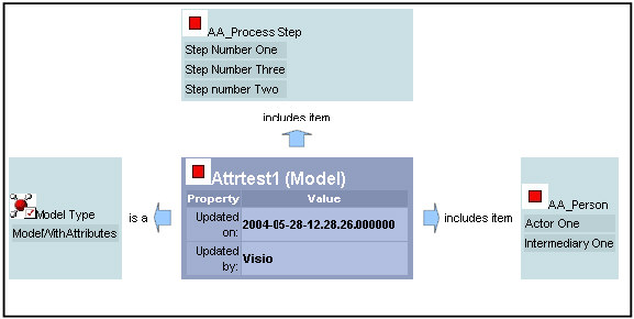
The "Model" concept is illustrated below, on the left is the EVA Netmodeler representation of a model instance called
"AttrTest1", it shows that this model is related to a "Model Type" called "ModelWithAttributes", and it includes instances of "AA_Process Step" and "AA_Person". The illustration on the right shows the corresponding Visio model:
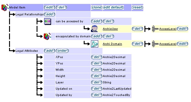
All relationships between EVA Netmodeler instances and a "Model" instance should have an infonode that can hold the
information regarding the object's co-ordinates and size relevant to that specific model.
The illustration below shows the info node definition used for this purpose:

Relationships between instances contained in a model
When the AGMCGI has to create a relationship between two instances that are contained in a model (for example "Step
Number One" and "Step Number Two" ), it needs to store the "connection point" information somewhere, as well as the
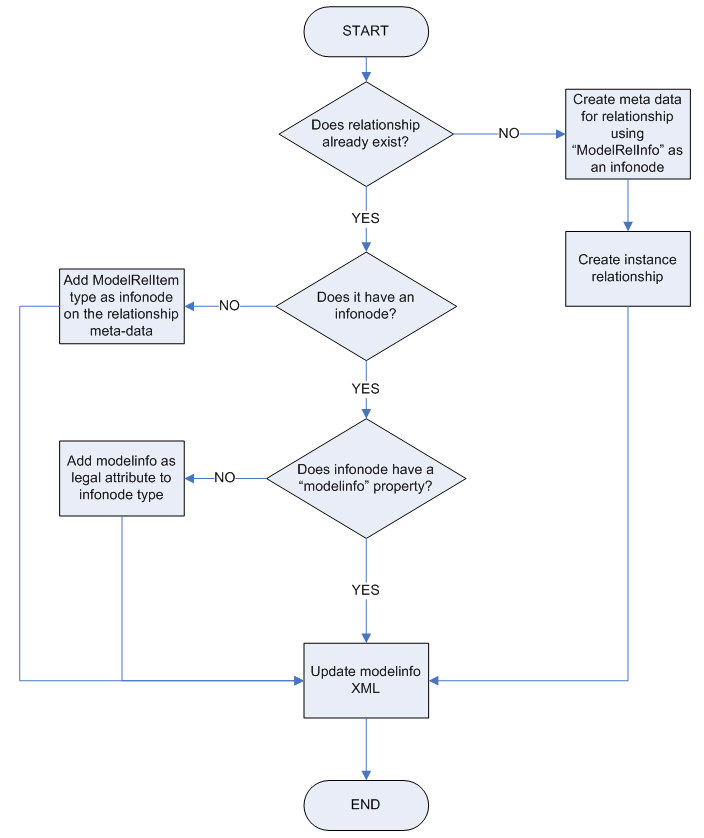
"connection text". A relationship between any two repository items may be represented on any number of models, even though there is actually only one logical relationship between the to elements. EVA Netmodeler
therefore stores all of the model specific information about the relationship on an info node on the relationship between the two elements.
This information would be stored using the following basic algorithm:
Below is an example of ModelInfo XML, fro this example it can be seen that the XML stores visual connection information
for multiple models in the same infomode. It stores the connection points and the connection text for each model.
<MODELRELINFO>
<MODELREL>
<MODELNAME>Attrtest1
</MODELNAME>
<FROMCONNPOINT>4
</FROMCONNPOINT>
<TOCONNPOINT>1
</TOCONNPOINT>
<MODELTEXT></MODELTEXT>
</MODELREL>
<MODELREL>
<MODELNAME>Attrtest2
</MODELNAME>
<FROMCONNPOINT>4
</FROMCONNPOINT>
<TOCONNPOINT>1
</TOCONNPOINT>
<MODELTEXT></MODELTEXT>
</MODELREL>
</MODELRELINFO>

|